3.2.4. Accelerator placement options
This section documents how to constrain accelerators to a particular Super Logic Region (SLR) in a device.
Accelerator placement is controlled through the user configuration file. See placement.
On an Alveo U200, which has 3 SLRs, external interfaces are placed as follows:
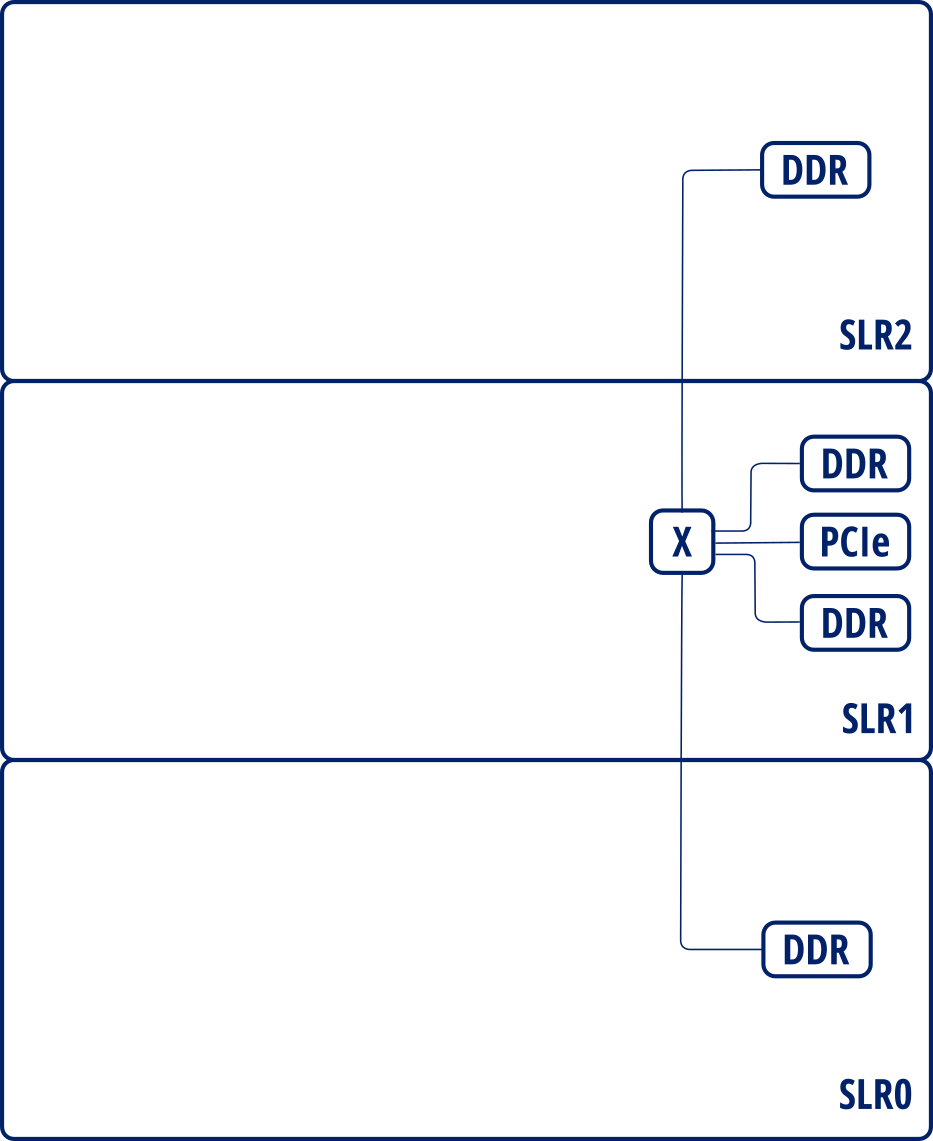
Interface layout for Alveo U200
By default, all user accelerators are placed as Vivado considers. Sometimes it places a kernel accelerator between 2 SLRs, usually negatively impacting timing. Users can enforce accelerators to be constrained to an SLR region in order to prevent it from being scattered across multiple SLRs. For instance, a user can specify something as follows:
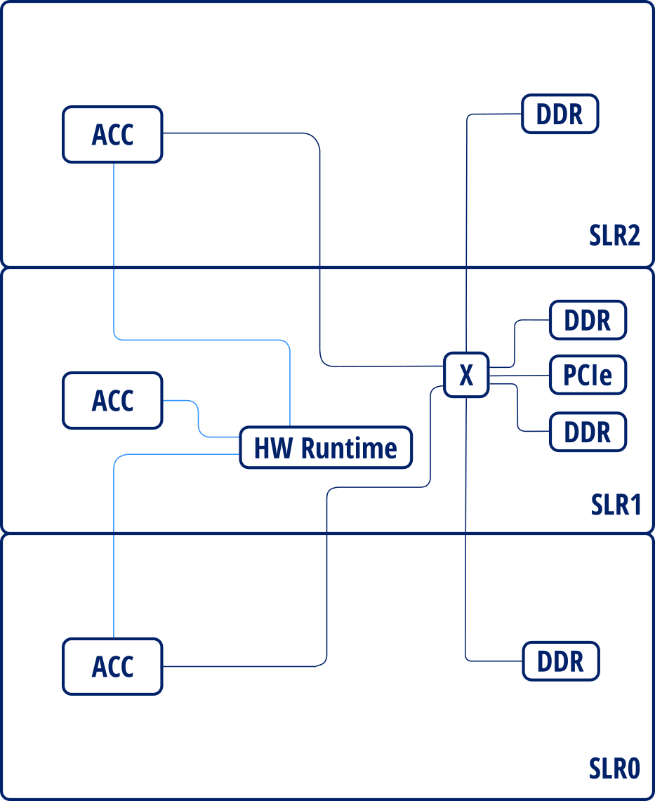
Placed instance diagram
Additionally, AIT adds register slices in the AXI and AXI-Stream interfaces of each accelerator and automatically configures those that cross multiple SLRs in order to insert pipeline stages to mitigate critical paths. For example, register slices added for the previous design will result in the following layout:
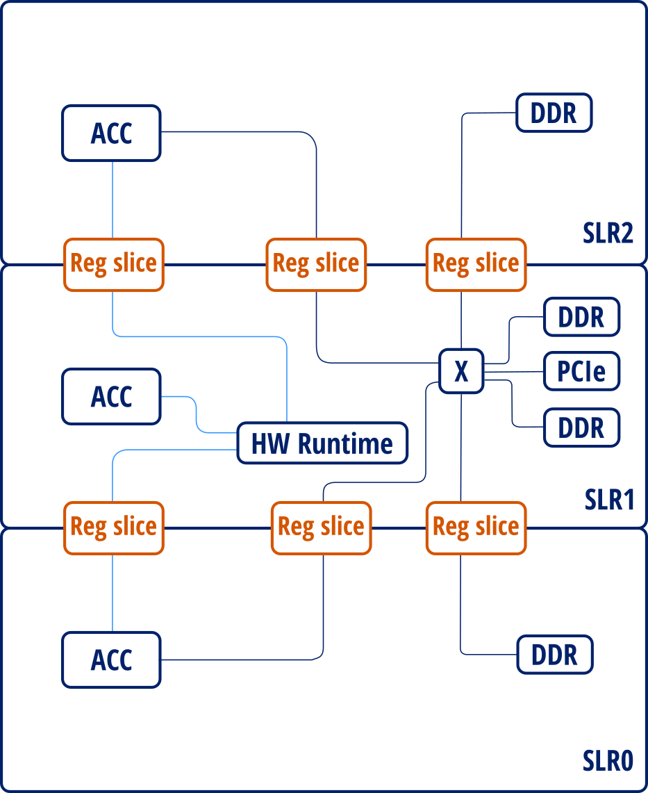
Placed instance diagram with register slices
Users can configure the number of pipeline stages to be inserted for each section of the SLR-crossing register slice (source, middle and destination) using either the global option --regslice_pipeline_stages or specify a per-instance configuration through the user configuration file (placement).